Robots have been steadily transitioning into human-populated environments and replacing physical separation from humans with complex perception and control software. However, current safety–oriented solutions are computationally expensive, prone to occlusion, and require a significant setup overhead. Robots are in need of compact, self-contained sensing of nearby space to guarantee safety at all times, improve perception, and afford rich interactions with their environment and people. In this work, we present the first novel prototype of a flexible artificial skin for collaborative robotics equipped with an inertial measurement unit (IMU) and proximity sensing. When a skin unit (SU) is first mounted on the surface of a robot, the exact location on the cover is unknown. To address this, we present a novel IMU-based kinematic calibration algorithm to reduce manual setup time. We then proceed to propose a proximity-based controller for online obstacle detection and avoidance.
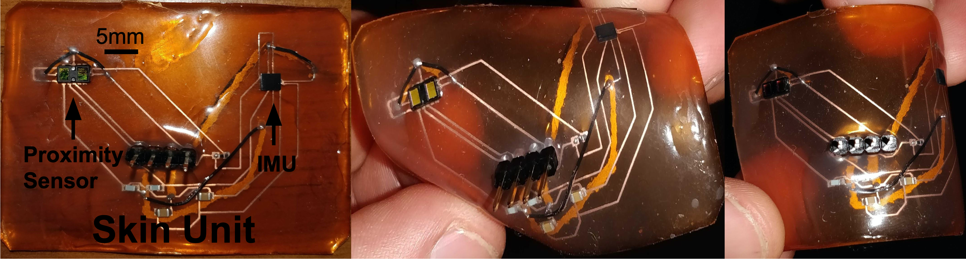
Figure 1. Flexible skin unit (SU) prototype created by etching the circuit diagram onto a copper sheet and then encasing it in an ecoflex polymer. The SU contains an inertial measurement unit (IMU) used to perform kinematic calibration, and a proximity sensor to detect objects in the proximity of the the robot surface.
Our long-term goal is to enable robots to sense their surroundings through heterogeneous sensors distributed along the robot’s surface. In order to efficiently utilize sensor information, we must develop a similarly distributed controller that generates robust and safe motions in presence of humans and environmental constraints. We plan to achieve our goal in three ways:
-
Create a flexible skin that can be attached to any robot arm and relays information about nearby objects in a plug-and-play fashion.
-
Develop a kinematic calibration algorithm to automatically, accurately, and robustly locate each skin unit mounted on the robot arm in parallel. This step is critical to ensure the robot knows where sensor data relates to with respect to its kinematic chain.
-
Formulate a robust controller that utilizes sensor information to plan trajectories that avoid undesired collisions and enable robots to work in close proximity with human collaborators.
Contents
Contribution
The contributions of this work are threefold:
-
Skin Unit: we present a new flexible artificial skin that can conform to multiple surfaces. The skin utilizes an Inertial Measurement Unit (IMU) and a proximity sensor to sense obstacles at a distance. Future prototypes will embed additional capabilities (e.g. pressure sensing, temperature sensing, tactile sensing…), toward a vision of heterogeneous tactile sensing similar to that of humans.
-
Kinematic Calibration: we present a framework for automatic kinematic calibration that leverages an IMU to accurately estimate the pose (position and orientation) of skin units, of arbitrary number, along the surface of a robot.
-
Controller: we demonstrate a control scenario where a robot arm utilizes proximity sensors embedded within a skin unit to avoid collisions when an object is nearby. We impose a repulsive force on the point the skin sensor is mounted on the robotic arm to ensure it will not collide with an object, but will still continue on a specified trajectory.
Skin Unit
Skin units are equipped with an IMU for kinematic calibration and a proximity sensor to sense nearby objects. We chose to embed our circuit in a flexible polymer called ecoflex in order to allow each skin unit to conform to the shape of the surface it is placed on. The figure below shows the flexible capabilities of the skin sensor.
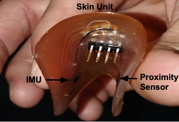
Figure 2. The Skin Unit (SU) prototype is equipped with an IMU and a proximity sensor and it is flexible enough to conform to a variety of robot surfaces and body shapes.
Kinematic Calibration
To automatically locate skin units along the surface of a robot, we utilize the angular velocity and linear acceleration measurements from the IMUs. Our optimization algorithm estimates the pose (position and orientation) of an SU using modified Denavit-Hartenberg (DH) [1] parameters as illustrated in Figure 3. The pose of each SU is estimated by six DH parameters with respect to the previous joint in the kinematic chain: four parameters from the joint to a virtual joint, and two additional parameters from the virtual joint to the SU (other two parameters are set to 0). A virtual joint is located within the link that is orthogonal to the joint’s \(z\) axis and the SU’s \(z\) axis. This solution is necessary to adhere to the Denavit-Hartenberg notation, so that each transformation can be expressed with no more than four parameters.
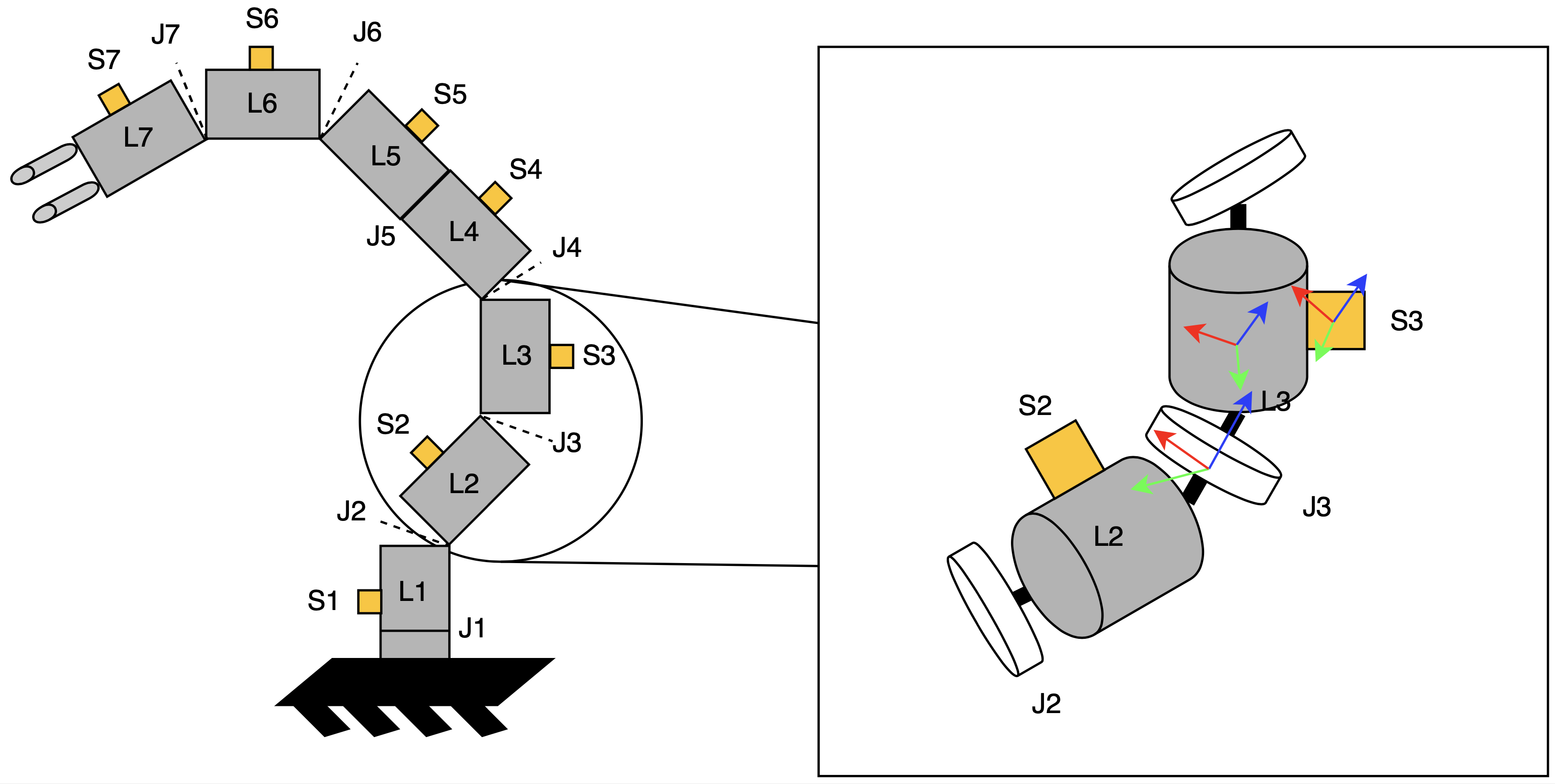
Figure 3. Depiction of multiple skin units (S) placed on the robots links (L) and separated by joints (J). We estimate the Denavit-Hartenberg parameters of each joint in order to calculate the pose of each skin unit along the surface of the robot.
Our optimization algorithm is composed of the following four steps:
-
Initialize a kinematic chain with randomized values. We represent each skin unit coordinate using a transformation matrix
\({}^0T_{SU_i} = {}^0T_1 \cdot {}^1T_2 \dots {}^{i-1}T_i \cdot {}^i T_{SU_i}, \quad \forall i\), where \({}^{i}T_{i+1} = \left[ \begin{array}{c|c} {}^{i}R_{i+1} & {}^{i}P_{i+1} \\ \hline \mathbf{0} & \mathbf{1} \\ \end{array}\right].\)
-
Collect Data. First, static forces applied to the IMU (that is, the constant acceleration due to gravity) are measured and compensated for. Then, each reference joint is moved through its operational range in a constant rotation pattern and the resulting acceleration as measured by the IMU is stored.
-
Define an error function. Acceleration exerted on each SU \({}^{SU_i}a_{u,d}\) can be estimated as a composition of local acceleration, tangential acceleration and centripetal acceleration:
\[^{RS}\vec{a}_{t a n_{u, d}} = ^{R S} \overrightarrow{\alpha_{d}} \times^{R S} \vec{r}_{u, d}\] \[^{RS}\vec{a}_{cp_{u, d}} = ^{R S} \vec{\omega}_{d} \times\left(^{R S} \vec{\omega}_{d} \times^{R S} \vec{r}_{u, d}\right)\] \[^{SU_{i}}\vec{a}_{u, d} = ^{SU_{i}}\underline{R}_{R S} \cdot\left(^{R S} \vec{g}+^{R S} \vec{a}_{t a n_{u}, d}+^{R S} \vec{a}_{c p_{u, d}}\right).\]Angular velocity \(\omega\) and angular acceleration \(\alpha\) are measured during data collection, whereas rotation matrix \(R\) and position vector \(r\) can be computed using the current estimated DH parameters. One example error function could be seen as the error between the measured accelerations from the IMUs and the estimated accelerations using the kinematic chain model for \(n_{pose}\) poses: \(E = \sum_{i=1}^{n_{pose}} \sum_{j=1}^{n_{joint}} ||a^{model}_{i,j} - a^{IMU}_{i,j}||^2\) (from [2]).
-
Minimize the error function with a global optimizer. A global optimizer optimizes the DH parameters by minimizing the chosen error function. We combine several different error functions to estimate both rotational and translational parameters. The final result in simulation can be seen in Figure 4.
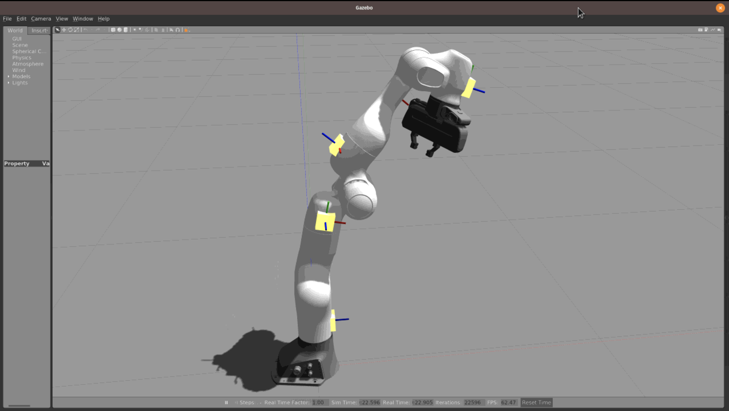
Figure 4. Calibrated IMU positions on a simulated Franka Emika Panda robot.
Controller for Safety-Oriented Human-Robot Interaction
Calibrated SUs can be used to locate obstacles in a robot’s environment; this information can then be utilized to modify the robot’s behavior in real time. When a robot detects an obstacle, it should continue along a trajectory as long as the proximity to the obstacle does not compromise safety. The robot should avoid the object if close, or stop if there is no way to complete the task while avoiding a collision. For this purpose, we present two separate obstacle-avoidance controllers, that focus on end-effector and whole body collision avoidance respectively (based on [3]).
End-Effector Collision Avoidance
The end effector’s operational-space velocity is modified with a potential field method [4] to avoid objects. A repulsive velocity vector (whose direction depends on the closest obstacle and whose magnitude is proportional to its distance) is applied at the end-effector to push it away from obstacles and avoid collisions. If an obstacle does not hinder the robot’s task, the original task-level velocity will be preserved. However, if the obstacle is too close the end-effector, its motion will stop completely. The repulsive vector’s magnitude is calculated by the following:
\[v=\frac{V}{1+e^{\alpha(\|\boldsymbol{d}\|\frac{2}{D}-1)}},\]where \(V\) is the max repulsive velocity, \(\boldsymbol{d}\) is the vector that goes from the end effector to the closest object and \(\|\boldsymbol{d}\|\) is that distance’s magnitude. The variables \(D\) and \(\alpha\) are user-defined and task-dependent.
The final repulsive vector \(\boldsymbol{V}(\boldsymbol{P}, \mathbf{O})\) points towards the object that is closest to the robots end-effector and is calculated by the equation:
\[\boldsymbol{V}(\boldsymbol{P}, \mathbf{O})=v \frac{\boldsymbol{d}}{\|\boldsymbol{d}\|}\]The following animation demonstrates end-effector collision avoidance where the end-effector is commanded to first move towards the robot body, avoiding the yellow obstacle point. The robot then moves towards the yellow obstacle, causing the robot to slow down to a complete stop at close proximity to avoid collision.
Whole-Body Collision Avoidance
To ensure safe human-robot collaboration, the robot must avoid collisions along the entirety of its body. Rather than directly modifying the end-effector velocity as in the previous method, repulsive vectors are used to apply kinematic constraints to joint velocities along the body of the robot. The constraints are computed using the following equations:
\[f\left(\|\boldsymbol{d}\|)\right)=\frac{1}{1+e^{\alpha \left(\|\boldsymbol{d}\|(2 / D)-1\right) }},\]where \(\|\boldsymbol{d}\|\) represents the distance form an arbitrary control point along the robot’s body to an obstacle as seen in the figures below. The rest of the equation is identical to the repulsive vector equation presented in the previous section, but \(f\) is now bounded between \(0\) and \(1\). The value \(f\) is used to limit the joint velocities in the two following equations. Depending on the closest object’s location either the maximum or minimum joint velocity \(\dot{q}_{i}\) will be altered.
\[\dot{q}_{\max , i}=V_{\max , i}\left(\left(1-f\left(\|\boldsymbol{d}\|)\right)\right)\right.\]
No collision avoidance: the robot's body collides with the yellow obstacle point
Collision avoidance: The robot modifies its trajectory to react to an obstacle near a control point and alters its joint velocities without hindering the end-effector task
Future Work
Dense Coverage of a Robot Arm with Skin Units
In order to consistently avoid obstacles around the robot, dense skin coverage is necessary. To achieve this goal, we must efficiently distribute wiring and computational resources along the surface of the robot. This has been accomplished by related work by using rigid printed circuit boards equipped with on-board microcontrollers and redundant connections (e.g. [2]). In this work, additional challenges arise due to the flexible and stretchable nature of our robotic skin that must conform to the surface it is placed on.
Our next near-term milestone is to densely cover a portion of a robotic arm with SUs and consistently avoid collision from any direction. This step will require a concerted system-level effort from hardware and electronics design (i.e. ensure measurement fidelity, reduce the amount of wiring, and allow a multitude of sensors to be placed on the robot with ease) to control and algorithm development.
Robotic Control Using Simulated Skin Units
In parallel to the aforementioned work, we aim at expanding our current controller to avoid dynamic and static obstacles using proximity sensor information in simulation. Simulated robotic skin will allow us to rapidly prototype different algorithms and easily share our work with collaborators that do not have access to the physical hardware. Simulated SUs will be represented by a uniform distribution of single-point laser scans emanating from the surface of the robot. Ideally, skin coverage will be automated to easily change coverage density.
Please email Kandai or Caleb if you would like to learn more about the current project, or would like to collaborate with us!
References
[1] Siciliano, Bruno, and Oussama Khatib, eds. Springer handbook of robotics. Springer, 2016.
[2] Mittendorfer, Philipp, and Gordon Cheng. “Open-loop self-calibration of articulated robots with artificial skins.” 2012 IEEE International Conference on Robotics and Automation. IEEE, 2012.
[3] Flacco, Fabrizio, et al. “A depth space approach to human-robot collision avoidance.” 2012 IEEE International Conference on Robotics and Automation. IEEE, 2012.
[4] Khatib, Oussama. “Real-time obstacle avoidance for manipulators and mobile robots.” Autonomous robot vehicles. Springer, New York, NY, 1986. 396-404.
[5] Mittendorfer, Philipp, Eiichi Yoshida, and Gordon Cheng. “Realizing whole-body tactile interactions with a self-organizing, multi-modal artificial skin on a humanoid robot.” Advanced Robotics 29.1 (2015): 51-67.